{=hardware=}
Irda Module project
If like me, you can't buy an IrDA module for your mother board, here you can find a simple circuit to build your own, hand made module.
Schematic
Bill of material
| Component | Value |
|---|---|
| R1 | 1K Ohm 1/4W |
| R2 | 100 Ohm 1/4W |
| R3 | 220 Ohm 1/4W |
| R4 | 10K Ohm 1/4W |
| R5 | 10K Ohm 1/4W |
| R6 | 220 Ohm 1/4W |
| R7 | 10K Ohm 1/4W |
| R8 | 10K Ohm 1/4W |
| R9 | 470 Ohm 1/4W |
| R10 (optional) | 19K Ohm 1/4W |
| D1 | OP131 (or compatible IR LED) |
| D2 | Green LED(used to monitor transmission) |
| D3 | Green LED (used to monitor reception) |
| T1 | 2N2222 (NPN) |
| T2 | 2N2222 (NPN) |
| T3 | OP845 (or compatible phototransistor NPN |
| T4 | 2N2222 (NPN) |
| T5 | 2N2222 (NPN) |
| T6 | 2N2222 (NPN) |
| IC1 | 74LS14 |
NB: The Base of T3 must be leaved disconnected to increase the gain)
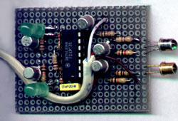
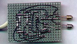
Prototipe photos
Schematic
If you want the original schematic, created with Arianna Draft, you can download ib by clicking HERE (197 downloads).
Notes
The circuit I developed, must be connected to the connector present on Pentium™ Mainbord TX and later.
Since the connector's pinout may change, you have to looking for correct pinout by reading your Mainboard user manual.
If your circuit can transmit, but doesn't receive, put a resistor of 10K Ohm between Vcc and RX. Some Mainboard do not have an internal pull up resistor.
If you want to use this circuit with Nokia Data Suite or another communication softwares, make sure you configured your IrDA port in Full Duplex mode.
Some BIOSes use other configuration options, like SIR or other.
Pay attention to choose the SIR mode (if available).
NB: I take no responsability for damages my circuit may cause.
PS: After IrDA upgrade, my PC works as usually, or better 


